TT3000 / TT4000
4G Modem Upgrade Procedure
Feedback
As part of Transponder Technologies Continued Improvement Program, we encourage any feedback for this document to be emailed to: support@ttfuel.com
All documentation becomes dated and at TT Fuel we are continually evolving our products and documentation accordingly. Unintentional technical or typographical errors are periodically corrected in later revisions.
Our current documentation convention is “DXXXXX-1”, where “XXXXX” is the document number and ‘1” is the revision level.
Disclaimer
All endeavours have been made to ensure information contained in this document is correct and accurate at the time of release. TT Fuel does not accept liability for any errors, omissions, or the use of information within this document.
If you would like to download this document, click on the link below:
4G Upgrade PDF Document - D00941-A 4G modem upgrade procedure for TT3000 or TT4000.pdf
Table of Contents
1.2 Before commencing upgrade - IMPORTANT
3.1 Upgrading box-mount low-profile antenna
1. Preliminaries
This document describes how to upgrade a 3G-only Cybertec modem inside a TT3000 or TT4000 DCA (Driveway Card Acceptor) to a 4G capable Teltonika model. This upgrade is required due to the shutdown of all 3G cellular networks in Australia.
Additional instructions are provided on how to upgrade the box-mounted low-profile antenna if necessary.
Please read through the entire document before performing the upgrade to ensure that all steps are understood and all tools and equipment required are available.
Note that these instructions apply to upgrading the modem in a TT3000 or TT4000 DCA only. Separate documents are available for other TT Fuel products.
For the remainder of the document, “DCA” will refer to either a TT3000 or TT4000 DCA.
1.1 Required parts and equipment
- Upgrade kit from TT Fuel as per below.
- A printed copy of these instructions, preferably in colour.
- Keys to open the door of the DCA.
- Keys to access the power distribution/switch board where mains power supply to DCA comes from if it is kept locked.
- Appropriate traffic management signs/cones/barricades.
- Due to the variability in the way modems have been mounted inside the DCAs over the years, it is difficult to provide an exact list of tools required however a general-purpose electrician’s tool kit with at least the following tools should be available:
- Selection of small to medium flat and Philips screw drivers.
- ¼” drive socket set with sockers ranging from at least 5-10mm.
- Small spanner set, which includes at least a 8mm open-ended spanner.
- If the box-mounted low-profile antenna is to be replaced, then a 1” (25.4mm) ring or open-ended spanner (preferred), or an adjustable spanner than can open to 1”, will be required.
- A torch or headlamp if lighting is poor.
1.2 IMPORTANT - Before commencing upgrade
Please note that when the modem upgrade has been completed, the support team at TT Fuel must be contacted so that they can switch over the management systems to use the new modem. To ensure that a member of the support team will be available to complete this task, it is required that a “4G switch-over” appointment be booked prior to commencing the upgrade. Failure to do this may result in the system being offline for an extended period until a support team member becomes available.
As soon as the upgrade kit is received, please email our support team at 4G.Upgrade@ttfuel.com to making a booking.
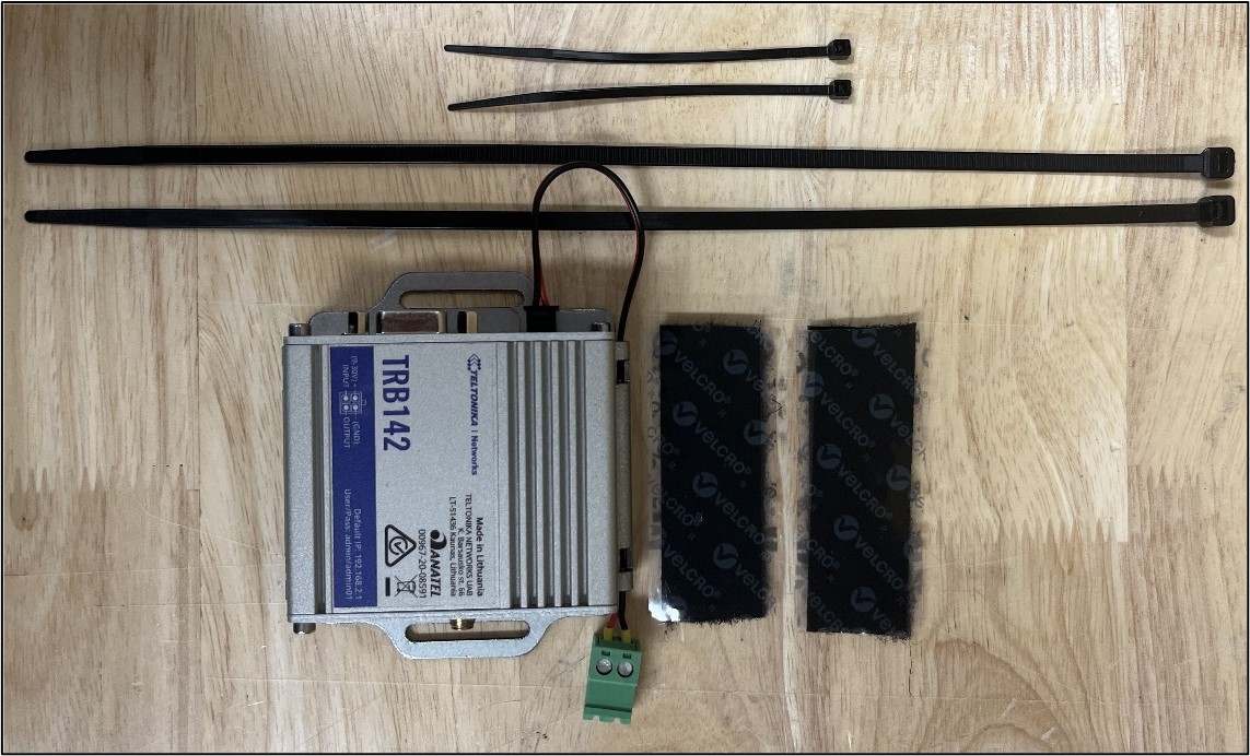
1.3 Upgrade kit contents
The upgrade kit is TT Fuel part number 097169. The contents are as listed below with the quantity that are supplied in the kit. Note that some parts are supplied pre-assembled.
|
Description |
Qty per Kit |
|
Teltonika TRB142 4G modem |
1 |
|
Modem SIM Card (preinstalled inside the modem) |
1 |
|
Cybertec SMM200 to Teltonika TRB142 adaptor bracket |
1 |
|
TRB142 Power Lead |
1 |
|
*Velcro strips with adhesive backing. Cut as two 7.5cm strips. |
15cm |
|
*Cable tie 300 x 4.7mm |
2 |
|
*Cable tie 100 x 2.5mm |
2 |
* These parts may or may not be used depending on the build of the DCA.
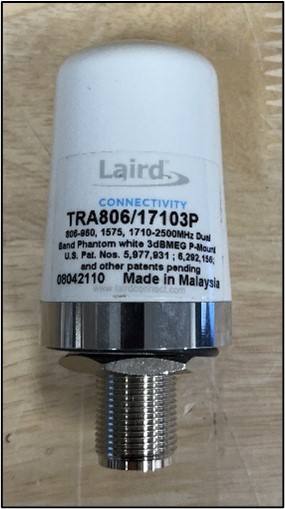
In addition, if it has been identified that the site also requires an upgrade to the box-mount low-profile antenna, then this will also be included in the kit.
|
Description |
Qty per Kit |
|
Box-mount low-profile 3dB gain Multi-band antenna - white |
1 |
2. Modem Upgrade Instructions
Step 1 - Apply appropriate traffic management and signage to ensure a safe working area around the DCA.
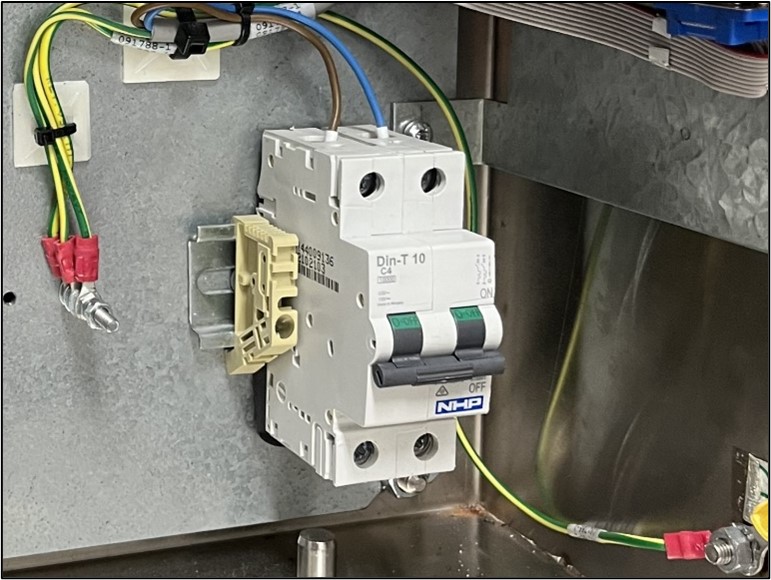
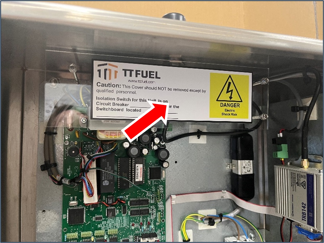
Step 2 - Isolate/switch-off power to DCA at site power distribution/switch board and lock-out to prevent accidental repowering. Please note that whilst this procedure does not require any connection or disconnection of terminals that have mains voltage levels, the DCA must be isolated from the mains supply to prevent any possible electrocution from accidental contact
Step 3 - Open DCA cabinet and switch off mains switch.
Step 4 - Disconnect all cables connected to existing Cybertec modem. Note that the antenna connector is secured with a backing nut which may require the use of a 8mm open-ended spanner to loosen.
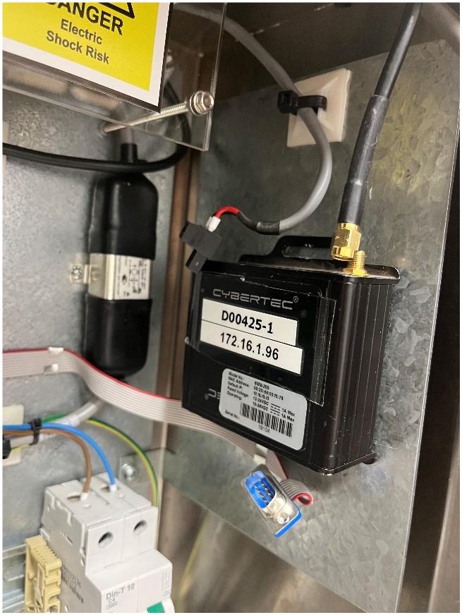
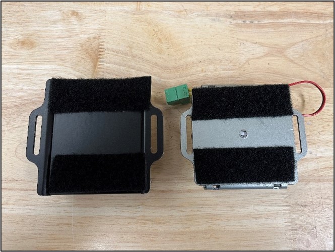
Step 5 - Take note of how the existing Cybertec modem is secured to the mounting plate as this has varied over the years. Some modems were secured using Velcro strips and some were secured using nuts or screws. Note that the photos shown in this document are of a modem secured using Velcro strips.
- If the existing Cybertec modem is secured using screws or nuts, then remove it and replace with the Teltonika TRB142 modem and adaptor bracket using the same fasteners and keeping the same orientation. The adaptor bracket supplied has the same mounting point dimensions as the existing Cybertec modem.
- If the existing Cybertec modem is secured with Velcro strips, then remove it by carefully pulling it away from the mounting plate. Separate the Velcro strips supplied in the upgrade kit into “hook” parts and “loop” parts. Take note which part (“hook” or “loop”) of the Velcro strip was used on the existing modem and place the same part of the Velcro strip on the back of the new modem adaptor bracket in the same orientation and spacing. Fit the new modem to the mounting plate in the DCA and press firmly for 30 seconds to ensure the adhesive on the back of the Velcro strip activates.
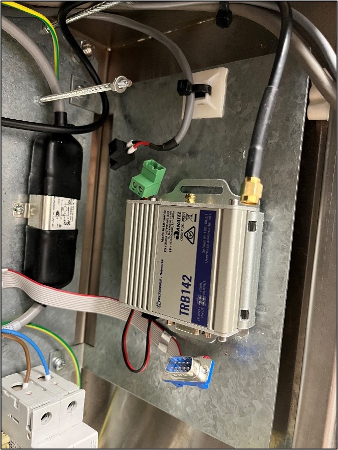
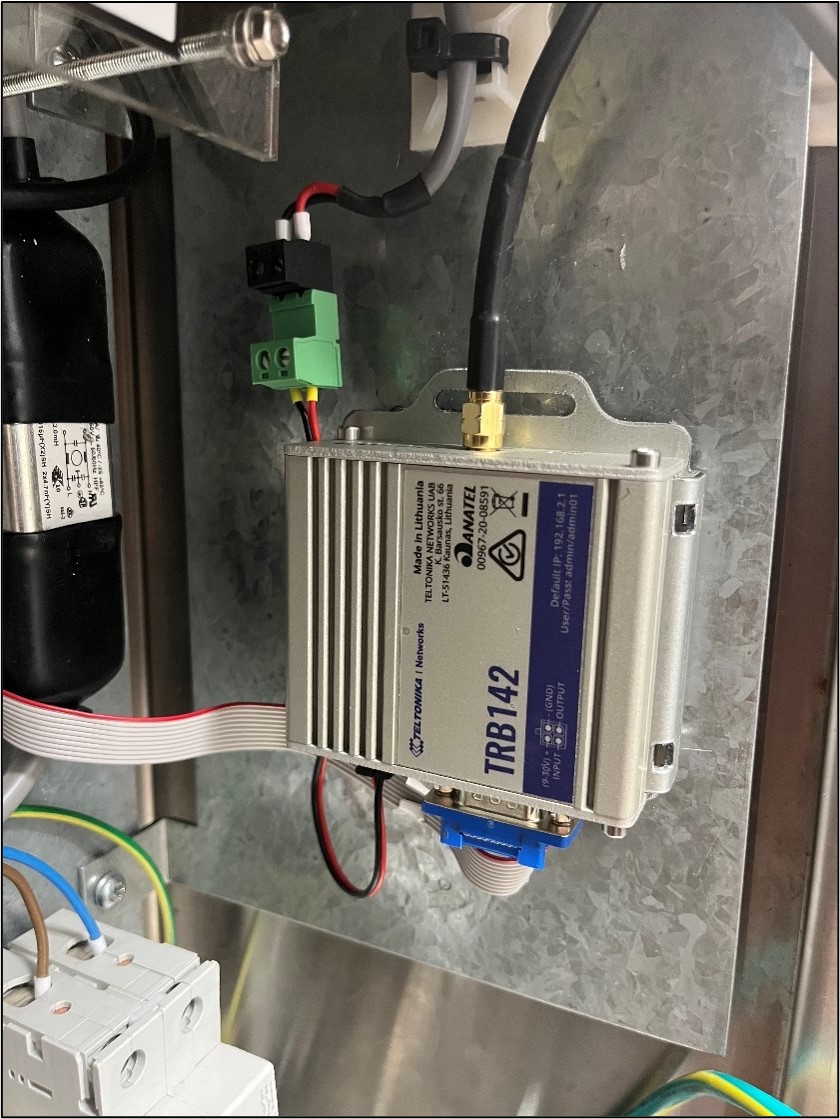
Step 6 - Connect the power lead, serial cable and antenna plugs to the new modem. Take partiuclar care with the antenna cable as it can be easily cross threaded so ensure it is properly aligned before tightening. Do up the backing-nut finger tight then use a 8mm open-ended spanner to “cinch” it tight.
Step 7 - If it has been identified that the DCA’s antenna box-mount antenna also needs to be upgraded as well then please follow the instructions in section 3 of this document and then continue to the with the following steps once completed. If the antenna does not require upgrading, then just continue to the following step.
Step 8 - Turn on the mains switch inside the DCA (the one that was turned off in Step 3) then restore power to the DCA from the power distribution/switch board.
Step 9 - Contact the support team at TT Fuel who will then switch over the systems to use the new modem and conduct a communications test. Contact details for the support team will be provided when a “4G switch-over” appointment is booked.
3. Antenna Upgrade Instructions
If the DCA is fitted with a black box-mounted low-profile antenna, like that in the photo below then it will require upgrading and a white multiband antenna should have been included in the upgrade kit.
If the DCA does not have a box-mount antenna then it, most likely, is using an external high-gain antenna. A determination whether this type of antenna needs to be upgrade at a particular site should have been made prior to the modem upgrade kit being ordered. Due to the many and varied ways these external high-gain antennas have been installed, it is not possible to provide specific instructions on how to perform an upgrade of this type of antenna. It is recommended that the customer engage with an appropriate professional to complete this task.
3.1 Upgrading box-mount low-profile antenna
Step 1 - Remove plastic shield, if fitted.
Step 2 - Loosen the backing-nut then unplug the antenna cable from the base of the antenna. Note that the backing-nut should only be finger tight but may require loosening with a tool e.g. pliers or multi-grips.
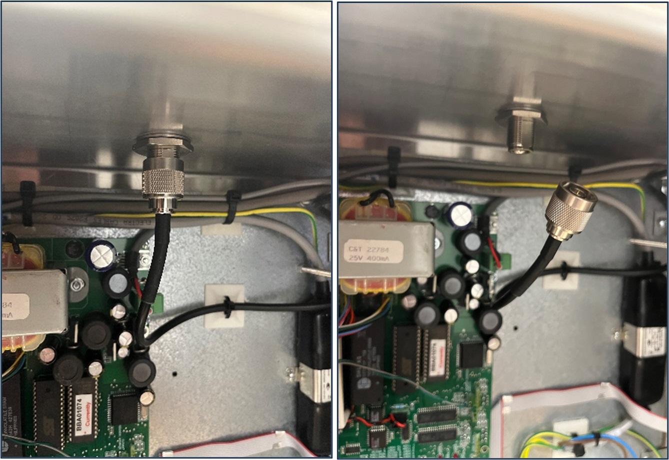
Step 3 - Loosen then remove the large nut and serrated washer that secures the antenna to the top of the enclosure. The antenna should then be able to be removed, though it may require twisting or tapping to release.
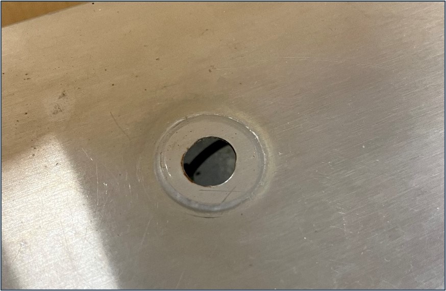
Step 4 - Clean the top surface of the enclosure around the antenna hole. It is important that this area is clean and free of debris otherwise the antenna may not seal correctly and allow water into the enclosure.
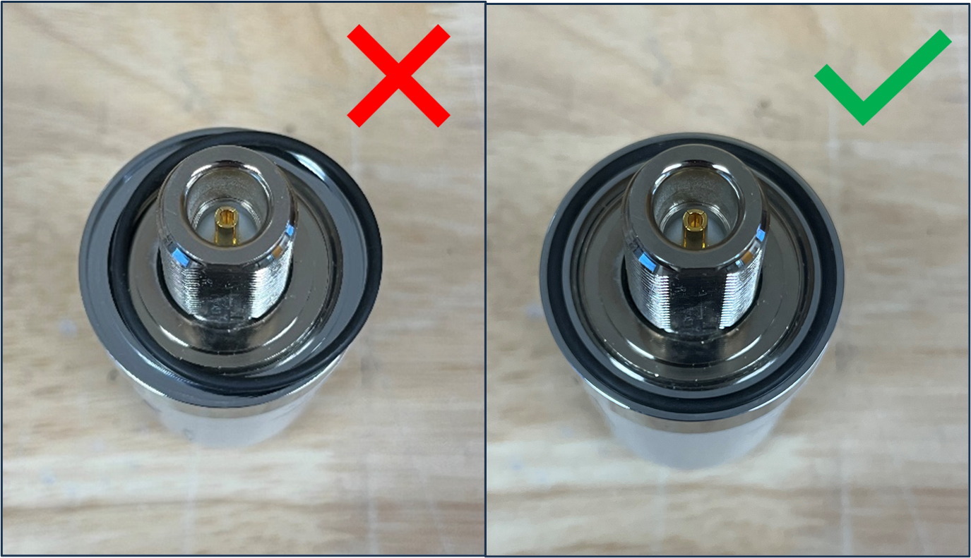
Step 5 - Remove the nut and serrated washer from the new antenna and then inspect the base of the new antenna to check that the O-ring seal is present and seated correctly in the groove. If the O-ring is not correctly seated correctly then water may enter the enclosure from the antenna hole.
Step 6 - Insert the antenna into the enclosure hole (making sure not to dislodge the O-ring) and then secure with the supplied serrated washer and nut. Hold the antenna securely whilst tightening the nut to prevent it spinning – if the antenna spins the O-ring may bunch up leading to it failing to seal properly.
Step 7 - Reconnect the antenna cable to the base of the antenna and hand tighten.
Step 8 - Replace the plastic shield removed in Step 1.